For quite some time I have been really interested in photography or video/filmmaking.
During my editing workflows I started to miss something to make it a bit smoother and easier.
Only working with the mouse and keyboard seemed to slow me down a bit, since I don’t do it on a daily basis, so remembering the keyboard commands was not an easy task.
So I did some research and found the ShuttleProV2, which really helped a lot in video editing.

After working some time with it and diving deeper into the whole filmmaking-topic, I stumbled upon color correction.
Of course it’s possible to do it with mouse and keyboard, but I’m a tactile person and I _REALLY_ like input devices with a lot of buttons, wheels and of course quite some displays and leds :D.
I knew, I would never really need a color correction panel for my hobbyist work, and the prices for these devices are too high to get one just for fun.
But when I stumbled upon a used Tangent CP200-BK on Ebay for a very, very great price, I couldn’t resist:
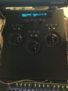
Since it’s an old, Ethernet based device, it’s no plug&play solution under Linux, but I already have a project (and working prototype code) in mind to make it working with KDEnlive.
But that’s an upcoming project and blogpost ;).
There are add-on panels available for the CP200-BK, to add more buttons and encoders, just like the actual Tangent Element series (Tangent Element). The price for the actual Elements Multifunction panel is quite high, but I really liked the concept of it.
Since I’ve learned quite a lot about input-related things during the simulator project, I thought it might be possible to build something like the Elements Mf, but a lot cheaper – and I was right 🙂
With a little research I found out that the Arduino Pro Micro shows to the OS as an Joystick-Device. This, on the other hand, can be used in Antimicro, to map Joystick inputs to Keyboard commands (or even macros or mouse movements). After some tinkering, the first working electronics prototype was done:
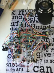
It consists of:
- 1 Arduino Pro Micro
- 4 128×32 pixel SSD1306 OLED displays
- 1 128×64 pixel SSD1306 OLED display
- 4 MCP23017 i2c I/O expander
- 1 TCA9548A 1-to-8 I2C Multiplexer Breakout
The software is:
- selfwritten Arduino code
- modified Antimicro sourcecode
To overcome the Micro’s shortcoming on I/O-pins, all inputs and displays are connected on the i2c-bus.
4 mcp23017 provide 64 additional inputs which are used as followed:
* 16: 8 digital encoders with 2 inputs each for CW/CCW rotation inputs
* 16: 16 momentary buttons
* 8: one momentary button in each encoders (mostly used to reset a configuration)
* 12: numpad with 0-9 and DEL and ENTER on it (to input timecode,…)
* 1: “Set” button, to switch between different sets in Antimicro.
That’s 53 total inputs used with some inputs left.
As with Tangent’s input consoles, a “Shift” button is implemented, which gives every input a 2nd function when pressed.
This button is directly connected to a digital input on the Arduino, since it only changes Arduino’s internal button status and does not send any command to the PC.
With 16 buttons and 8 encoders there are 24 functions available at once.
When using the Shiftbutton, another 24 functions are available, that’s 48 in total.
But that’s only the first set, since Antimicro gives you 8 sets to configure, that’s 384 functions per configuration.
That should be enough for every software I want to control.
(In case it’s not, there are still the 8 push-functions in each encoder, which adds another 64 total functions ;))
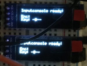
Since it’s quite hard to memorize all functions in each set, 4 OLED displays show the current configuration of each encoder and each button.
Configuration changes or changes of the current set will be send from Antimicro to the Arduino through the serial port in realtime.
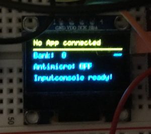
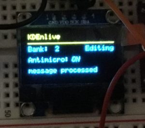
The 128×64 display shows the status of the Arduino, if it’s connected to Antimicro, which software configuration is loaded (since Antimicro can switch when changing windows) and what set number and set label are active at the moment.
When testing the CP200 there was one thing that really stuck out to me – as long as the softwareside is not connected to the panel after turning it on, it stays in a testmode, where you can check, if all buttons and encoders are working properly.
I liked that so much that I decided to implement it in my code.
Here’s the status display and 2 of the label displays in testmode:
Once Antimicro has connected to the Arduino, the displays change.
The yellow line on the status display shows the current active configuration in Antimicro, “Bank” shows the active set number and label.
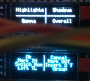
The upper encoder display shows the current function of 4 encoders (2 displays are used for the encoders), the lower shows 8 button configuration (also 2 displays).
Learning C++/Qt to adapt Antimicro to my needs was quite a challenge, but also a real pleasure. I always try to learn new things and although I hat a short look at C++ years ago, it took me quite some time to get used to it again.
There are some minor things to change in the Antimicro code (react to the Arduino getting unplugged or plugged in again), but otherwise, everything is fully functional.
In the next post I’ll discuss my design ideas for the overall hardware.